Realizing how old was my Brother KH-965 knitting machine, I knew that it was time to change its battery unit. But I didn’t like the idea of having to desolder and solder its battery unit each time it needed to be replaced.
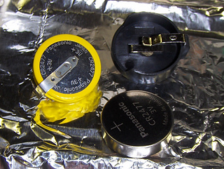
So, I came up with an idea to replace it from a 1-unit battery (yellow coated ring in first 3 photos) to a 2-unit battery. The 2-unit battery would consist of a holder and a coin cell battery (also showed in first 3 photos). This means that the holder would be soldered into the PCB (printed circuit board) and remains there permanently (4th & 5th photos). The coin cell battery would snap in and out of the holder for easy replacement (6th & 7th photos).
I called up Digi-Key, a reputable electronic component dealer in the US, and was referred to these 2 parts:
1. Battery Holder: MPD BH1000G (http://www.digikey.com/product-detail/en/BH1000G/BH1000G-...)
The 2 PC pins on the battery holder matched up with the old battery unit perfectly on the PCB.
2. Coin Cell Battery: Panasonic-BSG CR2477 (http://www.digikey.com/product-detail/en/CR2477/P120-ND/1...)
This battery can be purchased locally.
Please Note: These battery parts are for the replacement of the Brother KH-965 and KH-965i model only. I know for certain that the KH-930 and KH-940 use a different battery unit. A different holder may be available for these battery type and this same concept could be applied.
But then, I ran into trouble during the battery replacement. While desoldering and removing the old battery, I didn’t realize that one of its pin was soldered on both sides. There was not too much solder on the battery side but enough that it removed part of the copper pad along with the old battery. These copper pads are conductive signals on a PCB (http://www.sunstone.com/customer-solutions/circuit-board-...). When the copper is stripped off, it loses the signal that was intended for the mounted part. Thus, the soldering of a new battery holder failed in this incident. Repair can be done however.
I need to desolder the battery holder, connect the signal properly to the lost copper pad and resolder the unit again. On the plus side, if this is done correctly, I would not need to remove this unit again for battery replacement.
I will report back when I get a chance to do this repair.
To be continued….
Ahhhh, the smell of success is wonderful. The problem is fixed!
I desoldered the battery holder and removed it. Now, I could see better where it went wrong. I took more photos so I could zoomed in on my computer at the area of the lost copper pad. The signal from that lost copper pad lead to a tiny resistor (R12). It’s a power signal and fortunately, the trace was wide enough to help the repair going more smoothly. I reconnected the power signal to the lost copper pad and soldered back the battery holder. That repaired the issue created from previous work.
I assembled back all the parts and plugged in the unit. I tested the pattern settings and voila, the setting held up as usual when the unit is turned off and back on again (the reason of the battery existence).
The hiccup was cured and the idea worked beautifully!
PLEASE NOTE:
I’m not encouraging you to do this work yourself unless you have knowledge of electronic and PCB work. I’m only passing on an idea. It is your own choice to whether implement this idea or not. I will share my idea but will not take responsibility of your decision. It’s as simple as that. It isn’t as critical so please don’t make it into one!


 Entity60 notebook
  handspun
 queue
queue favorites
 friends
 needles & hooks
 library